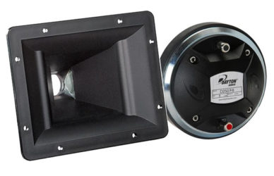
| Fig 1 shows the frequency response of the D250P/PH565 combo.
BLACK trace = RAW (no crossover) The CDEQ in my crossover is not activated. Microphone is 1 meter from tweeter, on axis. Gating at 5 msec. No smoothing applied. |
 (Fig 1) Frequency Response of Dayton D250P with Pyle PH565. Vertical Scale = 5 dB/DIV |
| Improper Summing
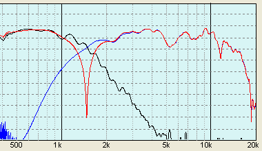
Fig 2 shows the summed response (Red trace) of a Dayton RS180S and the D250P/PH565 with the electronic crossover set at 1.5kHz (24dB/oct). A huge chuck of frequencies from 1.5kHz to 2.5kHz are missing. Cancellation is also observed at 2kHz. |
 (Fig 2) Summed Response of RS180S with D250P/PH565 |
| D250P in Reverse Phase
Wiring the D250P in reverse phase did not result in a deep notch. Instead, a chunk of frequencies from 1kHz to 1.7kHz is now missing. Now, the cancellation is on the left of the crossover frequency. This is an indication that the acoustic offset of the RS180S and the D250P is quite large. |
 (Fig 3) Summed Response – D250P in Reverse Phase |
| Applying Delay
With the D250P still in reverse phase, a delay is added to the RS180S. A deep notch (Red trace) in Fig 4 is observed when the delay time is correct. This notch will center at the crossover frequency of 1.5kHz. |
 (Fig 4) Delay Added to RS180S |
| Time Aligned Summed Response
Fig 5 shows the time aligned summed response when the D250P is wired back to normal phase. No cancellations are observed on either side of the crossover frequency. |
 (Fig 5) Time Aligned Summed Response |