|
SAE 3100 Power Amplifier
SAE (Scientific Audio Electronics) has a rich history in audio. This particular model, the 3100, was manufactured between 1976~1983. It is one of their smaller power units, rated at 50 Watts per channel into 8Ω. But don’t let this fool you. It is the quality of the Watts that important.
On removing the top cover, two pairs of TO-3 power transistors are clearly visible. They are soldered onto a long pcb with the voltage drive circuit on the left. Behind the front panel is the circuit board for the LED display. The power transformer is on the right, likely a toroidal housed inside a cylindrical metal container for shielding.

Is there any merit to the SAE’s fame? Perhaps a look at the SAE 3100 schematic may shed some light.
SAE 3100 Schematic
What is immediately apparent about this circuit is the symmetry. The top and bottom halves look exactly the same. Only the transistors are different. There is no official name for this kind of circuit but I like to refer to it as a Mirror Image topology.
Another interesting aspect that stands out is the arrangement of 2SA914 and 2SC1953. This is commonly referred to as the Lender’s Circuit. If I’m not mistaken, it is also known as a Folded Cascode.
It is remarkable that as early as 1976, they are already using this Mirror Image type of design. This circuit is quite demanding. Components must match otherwise it can de-stabilize the amplifier. The designers are so confident that they even find it unnecessary to incorporate any forms of output DC adjustment. Note that the SAE 3100 also has no over-current protection that can be detrimental to your listening pleasure.
Disassembling the SAE 3100

The SAE 3100 construction is very well laid out, an amplifier module, a power supply board and the LED display. The power supply board has two Elna 10,000uF/50V for the main filter caps. The relay and the components on the right is for soft-start and output DC protection.
When I received this amplifier, there was no sound from both channels. Now with the SAE 3100 uncovered, I checked the outputs before the relay for any DC. Both channels registered less than 10mV each. Impressive.
On the drive board, there are also no burnt components. This is a huge relief. It indicates that the transistors are not damaged. The likely cause of the problems point towards bad capacitors. After all, this amplifier is almost, if not 50 years old.
Power Supply Board

The first step is to tackle the power supply board. I replaced all the small capacitors with new ones. This is where it’s a pain to work on vintage amps. Some manufacturers have the habit of angling the capacitor leads 90° during soldering. The SAE 3100 is one of them.
This makes replacing the capacitors a delicate and time consuming exercise. Removing the old solder is not enough. All the leads must then be straightened back to vertical otherwise the capacitor will not come off the board. Forcing the capacitor out will most certainly damage the copper pads and likely the tracks as well.
After re-capping, I powered up the board and true enough, the relay clicked in. Fortunately, the relay contacts are still good, not pitted and blackened like some other vintage amps that I worked on before. The relay is a 48Vdc, DPDT type that I believe is still being manufactured.
There are no leakages with the big Elna capacitors and they are still holding their charge. That’s wonderful because replacing them would be problematic.
Now that all the voltages on the supply board tested fine, it’s time to check out the amplifier module.
Voltage Amplifier Circuit Board

The layout of the voltage amplification section is exemplary. Channel A and Channel B are exactly the same. All components are clearly marked. It is also extremely compact. And this is with a single sided board. Amazing.
Re-Capping the Amplifier Module

I started to re-cap Channel A first, the left half on the board. All five e-caps are replaced with the same values. The only change I made is with the caps at the input. The originals were polarized types. I wasn’t too happy with that and I replaced them with Non-Polars (the yellow ones).
Testing Channel A

I connected the supply board back to the amp module and powered it up. No oscillations, no high DC. So far, it looks promising.
I then injected a 1kHz sine signal to check the maximum voltage swing. It went all the way to the rails (84.8Vp-p). The amplifier remains stable even when driven into clipping.

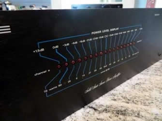
With both channels re-capped and bench tested into an 8Ω dummy load, it’s time to check on the LED display. Both Channel A and Channel B worked perfectly. Their LEDs came on one after another as the power increases, all the way to 0dB at full power.

SAE 3100 Fully Restored
With the the SAE 3100 fully tested, I reassembled the unit and put it back into service. It is now enjoying a new lease of life, together with a retrofitted AB Precedent 400.
I am fortunate that this amplifier has not been repaired before and all the transistors are still in good working condition. So what I’m hearing is essentially the original sound of the 3100. And I like it.

|