|
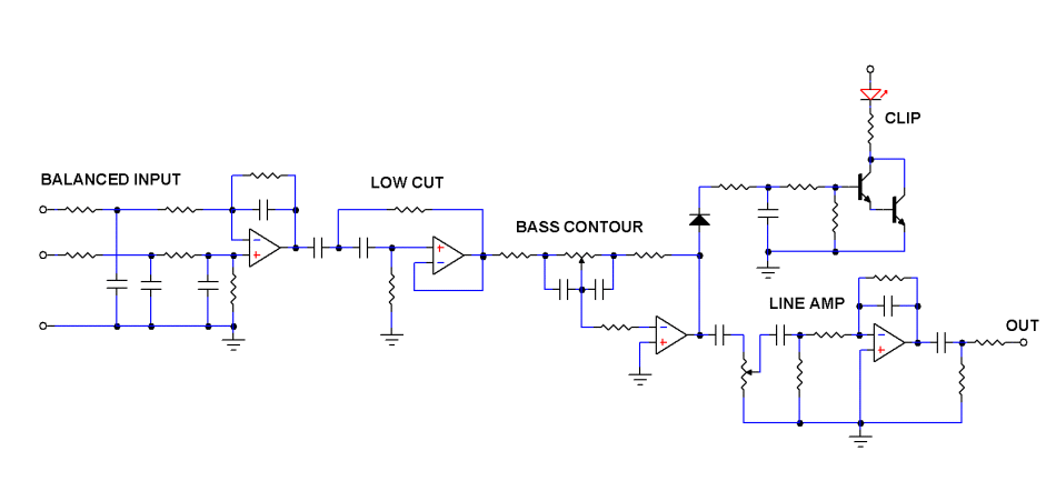
Part 2 – Testing Completed I wasn’t too happy with the first prototype board. While the bass attack and dynamics are correct, it lacks the extension. I then made another test board and shifted the low cut to 30Hz. Now the bass sounds correct. I’m ready to move on to the next stage, that is drawing out the pcb. Before I do that, I would like to explain the circuit in greater detail. The diagram above is the full schematic of the BassEQ board. For simplicity, I displayed one channel only. The actual pcb is stereo. Right at the front is a balanced input. This is useful for users whose source is far away from the BassEQ. For unbalanced use, just ground the inverting input. The 2nd and 3rd stages are the heart of the circuit. The low cut filter ensures the sub bass is not boosted when one turns up the bass with the baxandall bass control. The bass boost is +10dB while cut is -10dB. After that is the output line amp to interface with the power amplifier. The output has a volume control so that loudness can be adjusted. Lastly, I incorporated a clip indicator to warn users that the bass is clipping. When the red led flashes, it’s a signal to turn down the bass boost.
The finished pcb is double sided, 1mm thick FR4. I laid ground planes at the top and bottom. The gerber and drill files are already with the pcb maker. It should not be long before FedEx delivers them. My initial run is just 10 pieces. I need to limit the quantity in case I made a mistake in the drawing. Reason being that I don’t use auto-routing. My software has it but I prefer to draw all the tracks manually, point to point. Old school. Part 3 will be testing this new pcb out. If everything works as intended, the next step will be beta testing. Stay tuned. |
December 16, 2021Projects
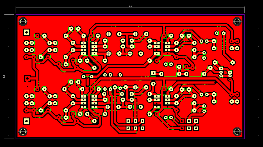 The last time I drew a pcb was in 2015. After being away for so long, I can’t even remember where to start. After I few days of trail and error, I redrew all my components and was ready to design the pcb.