|
LM3886TF “Overture” Amplifier The LM3886TF is very popular in the HiFi community. It’s the “Overture” series from National Semiconductor. It’s so highly regarded that even some high-end manufacturers designed their amplifiers based on these “Overture” chip amps. Now with DIY, you can own a high performance amplifier for a fraction of the cost.
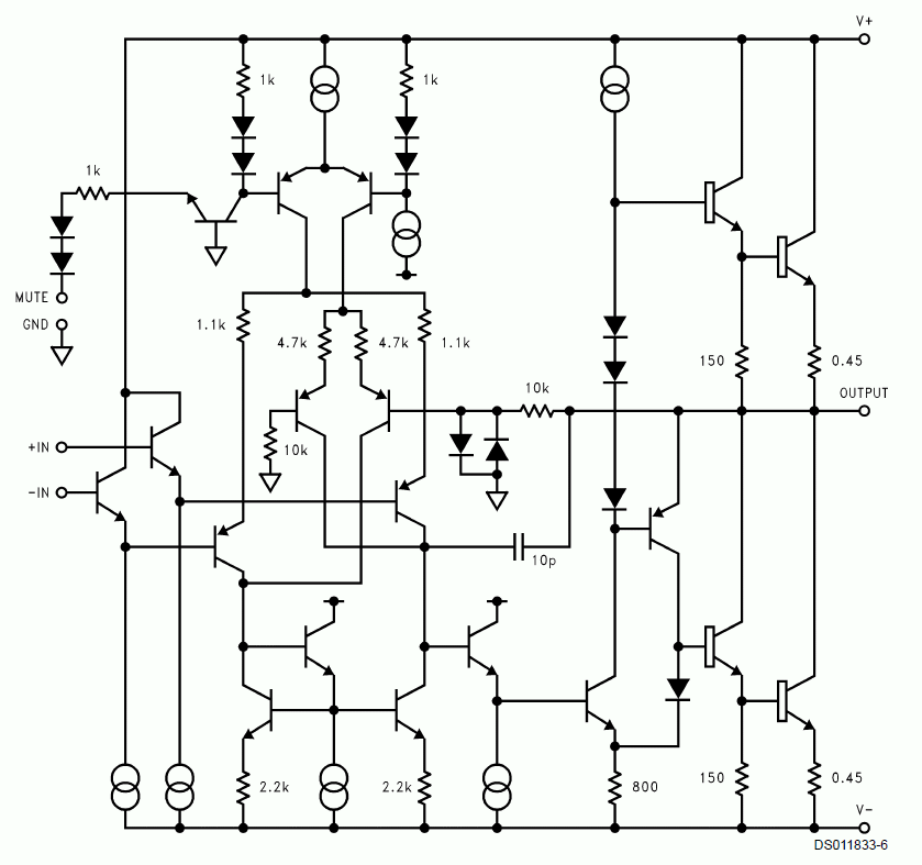
The LM3886TF datasheet has a simplified schematic of it’s inner workings. This will give us some idea of the way it’s designed, contributing to such impressive distortion figures. Sziklai InputRight from the start, we can see the design objective of the LM3886TF. The input is a Sziklai compound pair. This is similar to a Darlington as both result in a high gain input thus increasing input impedance. Current MirrorsThe LM3886TF uses active loads in the input different pair for high gain. But it’s not a simple current mirror. It is an improved version known as “Emitter Follower Augmented Mirror”. Darlington VASAll the benefits of a high input impedance and current mirrors would be lost if the VAS “loads” the input stage. In the LM3886TF, the signal from the input differential to the VAS is ‘Buffered”, this time with a Darlington. Looking at this from another perspective, very little current is used to “drive” the VAS. Quasi-Complementary OutputNow that the signal has been properly amplified, it’s time to inject it into the Current Stage. What jumps out is here is the top and bottom power transistors are both NPN. This is what is known as “Quasi-Complementary”. In other words, it mimics Full Complementary which uses NPN and PNP. One of the advantages of Quasi-complementary outputs is the two NPN transistors are the same electrically. Therefore matching them is much easier. More so when it is done as in an IC. MUTEThe LM3886TF has a MUTE at pin 8. I don’t quite understand the purpose of having a Mute function because the amplifier should be ON all the time when it’s powered up. The only time I would use it is to cut off the music when the LM3886TF is driven into clipping. That should wake up whoever is operating the system. But since it’s there, let’s take a closer look at how it works. From the schematic above, pin 8 is part of the current source in the first stage differential. When pin 8 is connected to 0V, it shuts off the current source. This in turn shuts down the input differential. To activate the current source, a minimum of 0.5mA must flow out of pin 8. To do this, wire a resistor from pin 8 to the negative rails (-V). With the negative rail voltage (-V) known, the resistance can then be calculated for a current >0.5mA. LM3886TF Power OutputAccording to their datasheet, the LM3886TF power output is 68W into 4 ohms with supply rails at (+-28Vdc). When driven into 8 ohms with the same rails, the typical power is 38W. This is clean, unclipped power (THD = 0.1% max). Using this as a guide, we can expect similar power output from the TDA7293. |

February 12, 2022Amplifiers, Projects
 Fig 1 – LM3886TF Equivalent Schematic