|
In this post, I’ll show how the Harrier can be designed as a passive speaker. This is what the majority of PA speakers are in the market. It’s popularity is partly due to convenience. Only one power amplifier is needed. No electronic crossovers, no adjustments for crossover frequency and no matching of compression driver and woofer sensitivities. Everything is done in the passive crossover. Just plug the speaker to the amplifier and that’s it.
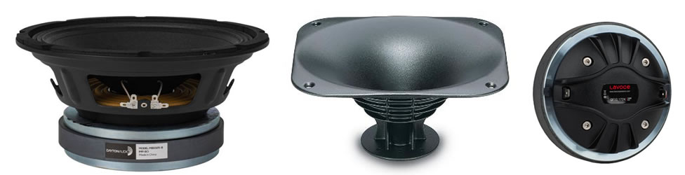
To refresh our memory, let’s have another look at the RAW frequency responses of the Dayton MB1025 and the LaVoce DF10.172K with the XT1086 horn. As in all designs where compression drivers are involved, my first step is to work on the compression driver. That is the trickiest part of the crossover.
The Red plot in Fig 2 is the horn combo with a passive high pass network. What is most obvious is the flatness in the response. But there’s more. I tuned the crossover turnover frequency to about 1.6kHz. Do not be mistaken that my electrical crossover is at this said frequency. It is actually higher than 1.6kHz. Fig 3 shows the MB1025 with her Low Pass network and the DF10.172K + XT1086 with her High Pass. Acoustically, they are crossing at about 1.8kHz.
The Black plot in Fig 4 shows the crossover passband. No destructive cancellations are observed in the crossover region. This indicates proper summing of the two drivers. Note that the deep notch at 2.5kHz from the MB1025 did not interfere with the summing. This notch has been a torn in my side from day one.
When I flipped the DF10.172K compression driver wires around, it resulted in a deep notch (Fig 5). It can’t get better than this. Compared to the active version, this passive Harrier has a far better alignment.
The final frequency response of the passive Harrier is in Fig 6. This is a much flatter response than the active Harrier. It’s not only just flat but notice how smooth the treble is. With a response like this, I would even use her in a recording studio.
The Waterfall plot (Fig 7) shows no anomalies. There are no meaningful artifacts in the treble.
The light blue slices in Fig 8 are the unwanted excess energy (artifacts). This plot is not as clean as the active Harrier mainly because in the active version, their crossovers are at 24dB/oct whereas in this passive Harrier, the slope is not as steep. Most of the unwanted energy is caused by the MB1025.
The Spectrogram in Fig 9 shows a very clean treble (3kHz~20kHz). The strongest streak is at 1.3kHz which is from a bump seen in the frequency response (Fig 6). It doesn’t last more than 5msec. Basically inaudible.
The Step response in Fig 10 displays an almost vertical leading edge, meaning “fast transient”. This is unusual in that the midwoofer is usually slower (see Step of Active Harrier).
This passive Harrier threw up a very interesting phase response (Fig 11). From 20Hz~20kHz, not once did the phase rotate. Generally, the MB1025 stayed within 120°. The horn combo is even tighter.
The passive Harrier Excess Phase (Fig 12) is quite impressive. Notice there’s no phase rotation from 20Hz~20kHz. It’s hard to get this with high order crossovers.
The passive Harrier distortion is surprisingly close to her active cousin. In the active Harrier, THD from H2~H9 is 0.702% whereas with this passive crossover, she is at 0.742%. No meaningful difference except for bragging rights. Mind you, in the active version, the crossover is 24dB/oct whereas this passive Harrier is lower.
The Harrier is a very friendly load for power amplifiers (Fig 14). She does not dip below 6Ω throughout her working range. Since she is a Closed Box design, there is only one impedance peak centered at 70Hz. Her electrical phase is not demanding. There is a dip of -60° at 100Hz and a rise of +40° at 2kHz. They will not stress a well designed power amplifier. Users should be aware than paralleling two Harriers would bring the impedance down to 3Ω. It is advisable to make sure power amplifiers are capable of this load so as not to trigger the over-current circuitry.
When I started working on this passive Harrier, I didn’t expect this level of performance. Even loaded into a 27 liters sealed box, she sounds wonderful. Surprisingly, the upper bass is loud enough, actually as loud as the midrange. What is lacking is the low bass but that is not what the Harrier is all about. She is meant for “Live” voice reinforcement. As such, an F3 of 80Hz is the target. The Harrier’s tonal balance is close to perfect. The vocals cut right through the music. That is my top priority. I really dislike muffled voices. Furthermore, the vocals are not shouty or screechy. Male and female voices are reproduced accurately. The treble is fantastic. Sibilance is well controlled. No harshness and very natural sounding. No titanium brightness. Neither does the treble sound dull or plasticky. The most outstanding part of this passive Harrier is the realism. I can actually hear the layers in the music. Backup singers are clearly separated from the main vocalist, like a knife cuts between them. The depth in the sound stage is unlike others too.
This is one design I’m very proud of. What started out as a PA speaker ended up in HiFi. This is quite an achievement. For home use, the Harrier is a boon for tube amp owners. With her high sensitivity, 1W can be pretty loud. In pro use, crossing at 1.8kHz seems a bit low for a 1″ compression driver. Because of that, there’s a fear that the DF10.172K may not survive the rigors of a band. This fear is unfounded because although the drivers are crossing at 1.8kHz, it is an acoustic crossover. The DF10.172K electrical crossover is much higher, so there’s ample headroom.
Fig 15 is the Transfer Function of the electrical crossover of the Harrier. The MB1025 and the DF10.172K are crossing electrically at 2.5kHz, not 1.8kHz This is the first time I’m showing any transfer function because I want to clear up any misunderstanding. People see an acoustic crossover at 1.8kHz and assume that’s too low. Wrong assumption. One needs to study the Transfer Function before making a determination.
I was getting some very high distortion with the MB1025 during playback. High enough to make my ears bleed. I don’t know whether the woofer takes a long time to break-in or there are some debris in the voice coil gap. There’s no way for me to check unless I cut away the dust cap. I have no idea whether this is an isolated case so bear in mind if you plan on buying this woofer. Apart from that, the MB1025 sounds superb. This strange behavior was first detected when I measured her Thiele & Small parameters. Unless otherwise stated, all measurements were made with the mic at 36 ins, tweeter axis. Impulse Window=5ms. No smoothing applied. |
September 22, 2023Drivers Evaluation, PRO DRIVERS
 Fig 1 – Blue plot=Dayton MB1025 RAW | Red plot=DF10.172K + XT1086 RAW | Tweeter Axis
 Fig 2 – DF10.172K + XT1086 with HP (Red plot)
 Fig 4 – Crossover PassBand
 Fig 5 – Null
 Fig 6 – Harrier Frequency Response
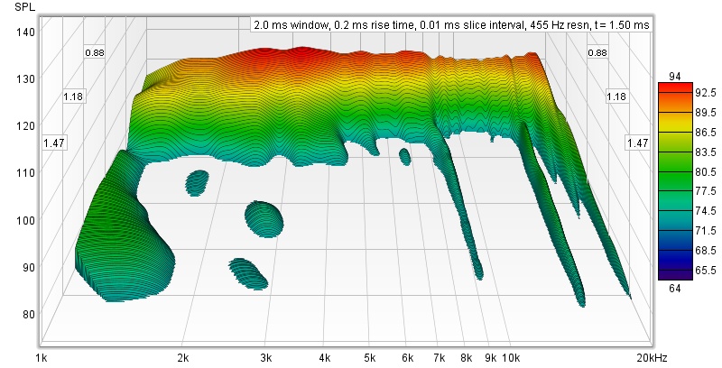 Fig 7 – Harrier Waterfall
 Fig 8 – Harrier ToneBurst Energy Storage
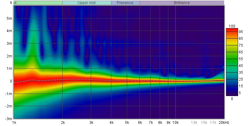 Fig 9 – Harrier Spectrogram
 Fig 10 – Harrier Step Response
 Fig 11 – Harrier Phase
 Fig 12 – Harrier Excess Phase
 Fig 13 – Harrier Harmonic Distortion
 Fig 14 – Harrier Impedance