Carver TFM-15CB
Now that my new lab is up and running, it’s a good opportunity to test the bench out. My first thought is to check out this TFM-15CB.
Fig 1 is the TFM-15CB with the top cover removed. I was relieved that she’s in stock condition. There are no signs of repairs, burnt marks etc, and fuses are still good. The entire 2-channels are on a single PCB. Layout is symmetrical. On either side are the heatsinks for the power transistors. Four power transistors are used per channel. Situated right in the middle is a smaller transistor for thermal control. The drivers are mounted on their own heatsinks. They are the four small heatsinks to the left of the output relay (blue). The two black 15,000uF 50V capacitors on the right are the power supply filter caps. The yellow film caps on the left are for the inputs. TFM-15CB Schematic
Fig 2 is the schematic of the TFM-15CB. The design is a proven two differential voltage gain stage, followed by a pair of drivers for the current outputs. No over-current protection is used, hence the output transistors will deliver whatever amount of current that’s asked. The downside is the power transistors can be damaged if the amplifier exceeds the power limits during use. I noticed no current sources are used in both channels. In place is a single voltage regulator seen at the top left of Fig 2. This regulator keeps the voltage constant at the emitters of both channels input differentials. Initial Bench Results The first thing I did on powering up the TFM-15CB is to check whether the outputs are blown. Fortunately, DC is only +20mV. This is excellent considering there are no DC offset adjustments or servos are used. I then checked the bias for the outputs and found to my surprise, they were a bit “lean”. One side was at 18mA while the other at 25mA. I monitored her for half an hour. Throughout that time, her bias held steady. That indicates her bias is stable. After that, I re-biased the two channels to 60mA per power transistor. Now, I can feel some warmth when I touch the heatsinks. Testing for Power Before I test the power of the TFM-15CB, I checked the secondary voltages of the transformer. It read 38-0-38 VAC. After rectification, it was 51.5-0-51.5 VDC. That’s the rail voltages for the amplifier. There is another secondary winding that read 0-12VAC. After rectification, it’s 14.8 VDC. That is the supply for the relay and the light bulbs in the VU meters. Now that I got the power supply measured, I hooked up a 4Ω 200W resistor to the TFM-15CB to test her power output. I set my Tektronix CFG250 Function Generator for a 1kHz Sine signal. I slowly increased the input voltage, keeping a close eye at the scope for signs of oscillations. It was clean all the way to clipping. Just before the amplifier clipped, the output read 26.4VAC. This worked out to 180W RMS into 4Ω. The input signal was 1.0 V. Both channels measured the same.
With the 1kHz Continuous Power established, I moved on to the 10kHz Square wave. Fig 3 is the 10V peak-to-peak display. There are no signs of overshoot or instability. TFM Concept Carver’s TFM stands for Tube Transfer Function Modified. Basically, TFM amplifiers were designed to emulate the sound of certain vacuum tube amplifiers. Whether you agree she sounds like a tube amplifier or not, I leave that up to the individual. Sound is after all subjective. However, engineering is not. There is nothing in the schematic (Fig 2) that indicates anything special. The TFM-15CB is a very conventional circuit. Many power amplifiers have similar circuits. I am inclined to view this TFM labeling as more of a marketing gimmick. My premise has always been, “if you want the sound of a vacuum tube amplifier, buy a vacuum tube amplifier”. Don’t expect a solid state amp to sound like a tube amp. They are fundamentally different. The Dreaded HUM When I tested the TFM-15CB on the bench, everything was fine. I then proceeded to play music and to my horror, there was a loud hum. I thought perhaps the power supply caps needed changing. But when I put her back on the bench, the hum disappeared. This was downright annoying. I was about to abandon this amplifier because I don’t want to invest more time trying to find the fault. There are other more pressing projects that need my attention. Having slept over it for a day or two, it occurred that it could be a grounding issue.The TFM-15CB has only a 2-prong power plug. There’s no Ground pin. When I took a closer look, it appears the input RCA ground is not soldered to the PCB but hard wired to the chassis. I can modify the grounding but that would be too troublesome. Instead, I grounded the chassis to Mains Earth. Problem Solved. No Hum after that. |

June 12, 2025Amplifiers, Electronics
 Fig 1 – Carver TFM-15CB
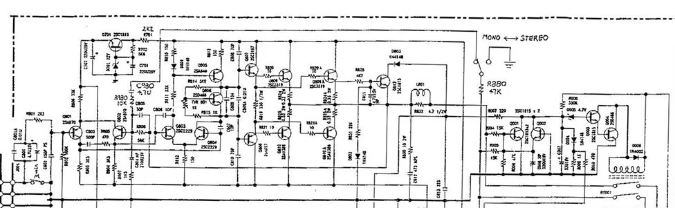
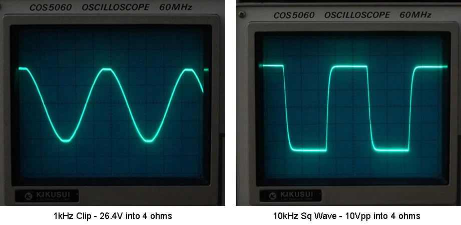 Fig 3 – Carver TFM-15CB Power and 10kHz Square Wave