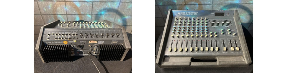
Electro-Voice 100M Entertainer
EV 100M Power Amplifier
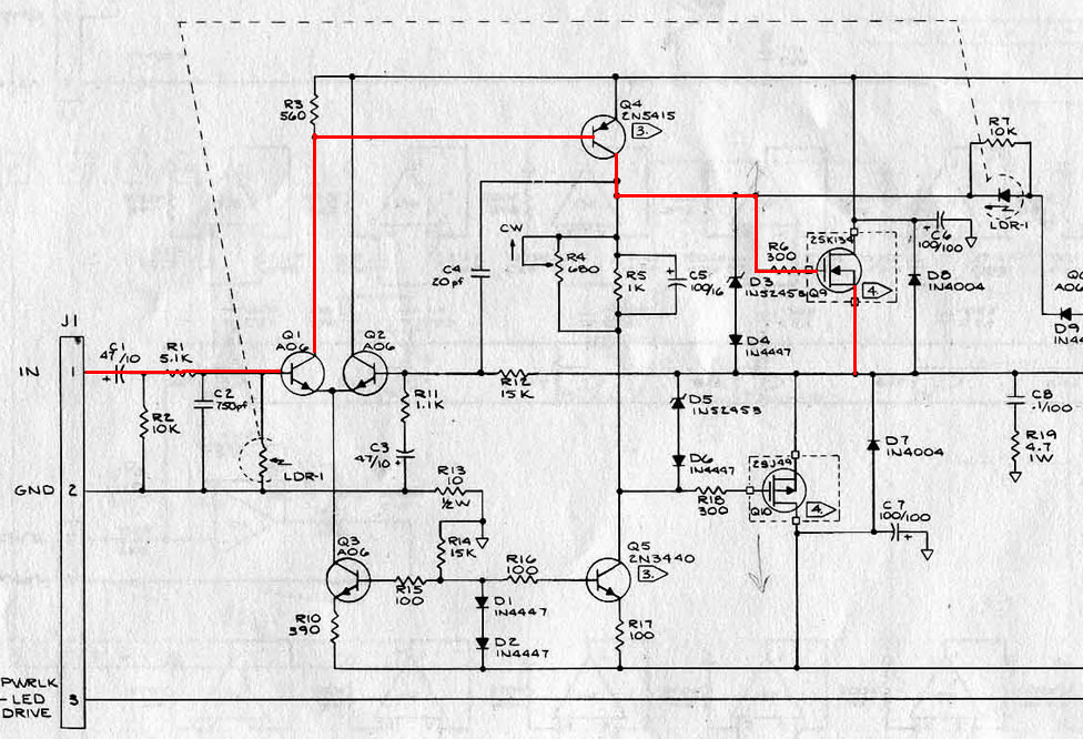
When I first looked at the EV 100M schematic, I was stunned. She uses 2SK134 and 2SJ49 lateral mosfets for power outputs. In the early 80s, these Hitachi mosfets were very costly. Not an issue in domestic HiFi but to see them in a PA powered mixer, it’s rare. One of the unique characteristics of lateral mosfet is they have Negative Temperature Coefficient. In simple terms, they are immune to Thermal Runaway. In Fig 1, the Red line is the signal flow through the amplifier. Starting from the input at left, the incoming signal is fed to an input differential pair with a current source pulling a total of 1.5mA. That means 0.75mA for Q1. The signal is then tapped off the collector and fed to the base of Q4. This is the Voltage Amplifier Stage or better known as VAS. This is where most of the amplication takes place. The standing current in this stage is 6mA. Note that there’s only a variable resistor to bias the mosfets. No thermal controller is needed because of the mosfets Negative Thermal Coefficient. The amplified signal in the VAS is then injected to the gate of the power mosfets via a 300Ω gate resistor. This gate resistor prevents the mosfets from breaking out into oscillations. Prior to the gate resistor is a 15V zener (Q3) in series with a small signal diode (Q4). These diodes prevent the mosfet from damage due to over-voltage. An interesting feature is the use of a Light Dependent Resistor (LDR). It is located right at the base of Q1 (LDR-1). My guess is when the amplifier clips, this LDR is activated thus shorting the signal to ground. It acts like a crude compressor. Personally, a better solution is to use a Vactrol but they are costly in comparison. Is there room for improvement? Definitely so. When I am fit enough to work on this powered mixer, I will retain the amplifier’s topology but upgrade all the transistors to modern ones. Moreover, I will re-tune the amplifier to HiFi quality. Till then, this 100M will be in storage but will be the first in line when I fully recover. I am quite excited with the prospect of upgrading this 100M. When I’m through with it, the performance will be unbelievable. |
July 24, 2025Amplifiers, Electronics