Peavey CS1000X
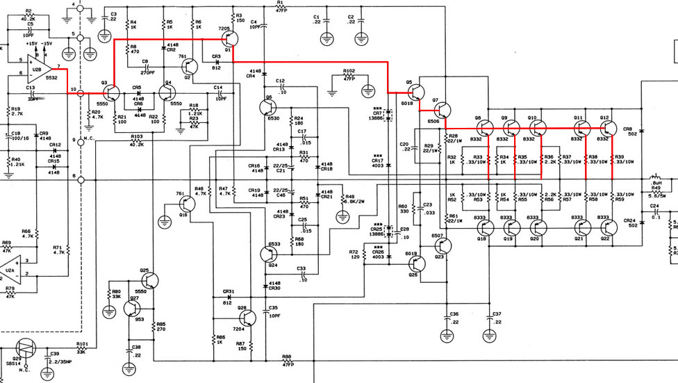
While I can’t find any information as to when the CS1000X was introduced, I found a Peavey literature for their CS1000 and it is dated 1992. The CS1000X is similar to the CS1000 so she can’t be far off from 1992. In the solid state world, there were a lot of advances in the development of transistors since 1976. Let’s see what the CS1000X is all about. Peavey CS1000X Circuit wise, I cannot find any weaknesses in the CS1000X (Fig 1). The input differential drives the VAS which in turn a darlington drive the five power transistors. Standing current in the differential is about 1mA per leg. Collector load is a 1kΩ resistor. Thermal control for the outputs are by diodes, five in total. There’s no provision to adjust the bias.
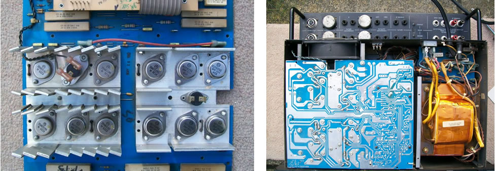
Fig 2 – Inside the CS1000X Fig 2 shows the PCB module and how the CS1000X is assembled. On the left are the minuscule heatsinks used for the power transistors. If the fan at the rear dies for some reason, the outputs will overheat. On the right is the full assembly. To fit the two modules into the chassis, one is inverted. This can be seen through the grill on the front panel. This technique is also used in the QSC 1700. There is one redeeming feature in the CS1000X and that is the power transformer. She is suitably sized for the power output and she has EMI shielding. This transformer is where the bulk of the weight is. Summary The CS1000X is a robust and reliable amplifier that is able to push out the power as advertised. At 8Ω, her rated power is 300W. At 4Ω, it’s at 500W continuous. Mono Bridged is at 1,000W into 8Ω. The only difference between the CS1000 and the X version is the latter version is specified down to 2Ω at 350W. The circuit remains the same as well as the number of power transistors. I caution the use at 2Ω. More power transistors need to be added to drive such a low load. With the present number of power transistors, you’ll be stressing the outputs and that can lead to premature failure. |
August 10, 2025Amplifiers, Electronics