Precedent 400
Precedent 400 Fig 1 is the schematic of the Precedent 400. As can be see, she adopted the mirror image typology. In my opinion, this is an overkill for a PA amplifier. Personally, I would use something simpler. Right at the input, the signal is met by two differentials (Red line). They decided not to use a Constant Current Source but a zener instead. The amplified signal goes to the VAS for the main amplification. In this stage, another transistor is used. This could be mistaken for a Current Source.but actually, she acts as a protection for the main VAS transistor. In the event of a fault, this transistor will shut off the VAS transistor, thus preventing it from damage. After the VAS, comes the Current Stage. No amplification is involved here. What we want is the most efficient way to get the power transistors to deliver current to the load (speakers). For that, they opted to use a Darlington configuration for the drivers. Note there are two transistors there. The first one is a Pre-driver followed by the Main driver. The advantage of doing this is very little current is needed to drive the power transistors. Therefore when the amplifier is pushed to the max, the outputs will not “load” the VAS.
Fig 2 shows the construction of the Precedent 400. Most obvious is the use of an angle bar for the power transistors. This angle bar connects the two heatsinks together for better heat transfer. All the power transistors are mounted there. Also can be seen are the Pre and Main drivers as well as the Thermal controller. A single large PCB accommodates the two channels. The PSU filter capacitors appear to be two units of 6800uF/80V types. This is a bit weak for two channels. Also, the power transformer at the bottom right.appears slightly undersized. Summary The Precedent 400 is a good candidate for updates. I would replace all the transistors with modern ones. The T0-3 power transistors are no longer available but MJ15024/25 can be used. They require more attention to “voice” though. If not done properly, they can sound rough.Either that or replace them with the plastic flatpack types like the 2SC5200/2SA1943. With regards to the pcb, I would rather design a new one. After 50 years, capacitors dry up, solder joints fracture and when you replace a component, you’ll likely damage the track underneath. Been there, done that. Another way is to re-purpose the amplifier. I retrofitted a Precedent 400 with one of my mosfet kits in 2018. Took me less time than to rework the circuit and design a new pcb. |

August 20, 2025Amplifiers, Electronics
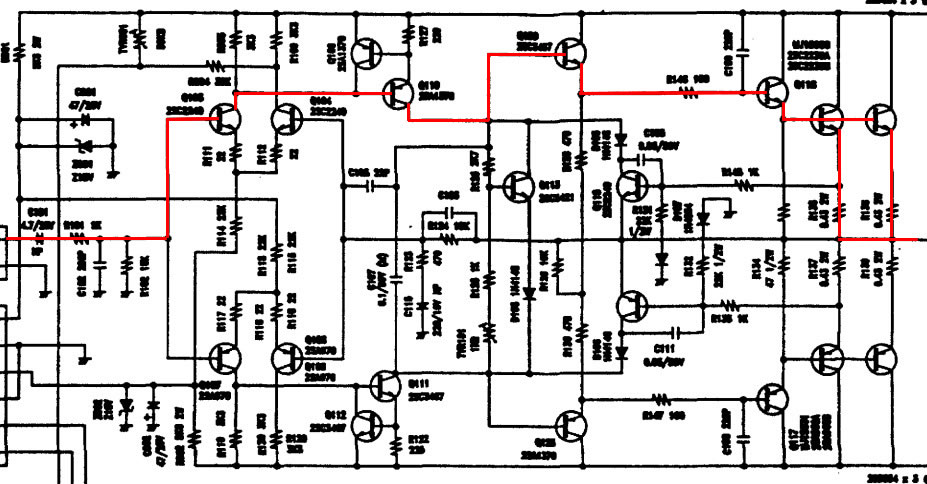
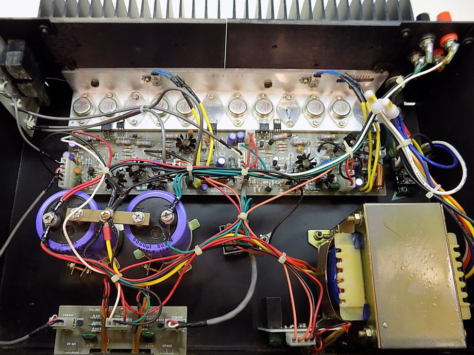 Fig 2 – Inside the Precedent 400